Installing Helical Cutterhead in Ridgid TP1300 Planer

I've owned a Ridgid TP1300 "lunchbox" style planer for at least 18 years and it's been quite reliable, despite the low price. However, like most planers with steel knives running the length of the cutter, tearout in highly figured wood is common, even with a set of fresh blades. And it runs LOUD. So I've long intended to either swap out the cutterhead for a Shelix or similar helical replacement, or buy a new planer with a helical head, perhaps recouping a little of the cost by selling the Ridgid.
Although purchasing a new planer was my initial thought, upgrading to a wider floor-standing model, the cost of these is very high - for example Grizzly 15" planers are north of $2000, and other reputable manufacturers are still higher. Furthermore, I rarely have the need to plane wider than 13", and space in my shop is tight.
Grizzly does sell a 13" lunchbox style planer with a helical head - the G0940 - for about $800 plus shipping, I was tempted to purchase that one, as I figured infeed and outfeed rollers on my old planer are not going to last forever and parts are hard to find, but the reviews I read on the cutterhead of the G0940 compared to the Shelix I was looking at were a little unfavorable. In any event, I decided to purchase a Shelix or similar highly-rated cutterhead.
While the Shelix was slightly less expensive, I purchased a Luxcut III for $550 from MyWoodCutters.com, mainly because the Shelix was backordered and the Luxcut was in stock.
The Luxcut helical cutterhead arrived cradled in a nicely made small wooden crate, along with a few replacement cutter inserts and tools to change out cutters. I probably was a little naïve in assuming that instructions for how to extract the old head and put in the new one would be included. However, there was a link on their website to a short description (1.5 pages, no photos) of the operation for a Shelix head (I am fairly certain the procedure is identical for the Luxcut). A search of the web for additional instructions turned up a number of discussions but no step-by-step instructions.
I took photos as I followed along with the disassembly instructions, so that I would have documentation on how things are put together before taking them apart (put to good use later!). As I proceeded, I began to have issues with the recommended procedures, some of which seemed plain wrong, others ill-advised. At some point I essentially abandoned these written instructions, took my own notes, and came up with what I feel is a more rational approach approach. I am offering that here as a photo essay to any woodworker who is trying to accomplish the same task.
________________________________________
INSTALLATION INSTRUCTIONS
Before starting:
You will need the following tools before starting:
- 4mm and 5mm Allen wrenches/keys
- 8mm open end wrench
- 22mm and (optional) 24mm socket wrench heads (for cutterhead pulley retaining nut)
- deadblow mallet and scrap wood for pounding on various things, including a specifically sized piece (ca 12"x1.5"x 0.5") for preventing the cutterhead from turning when removing end nut.
- spring retaining clip pliers with appropriately sized tips (for removing chain-drive cogs)
- vise grips or crescent wrench for removing worm gear from one end of old cutterhead
General advice:
- keep track of all hardware removed in some organized fashion, so that you can find things later and know where they go
- keep shop vac and shop towels handy. Whenever a new area inside planer is exposed or part removed, vacuum or wipe down as appropriate. There's plenty of spots where wood chips or dust can collect.
- consider rubber gloves for the especially greasy task of removing chain drive assembly. Or plan several trips to the sink with degreaser for hands.
- leave the plastic wrap on the helical cutter head, except where it may be covering the bearings, or wrap cardboard around the cutters, to protect your hands when installing.
PROCEDURE:
Disconnect dust collection hose, unplug planer, remove the 4 hex-head bolts holding planer to stand (at four corners, one marked with yellow arrow, another already removed).
 \
\Move planer onto benchtop
Remove the three thumb screws holding the dust chute on the back of planer and remove the chute, set aside. Cutterhead is now exposed.

Carefully rotate the cutterhead until it locks with one blade exposed, then loosen all seven grub screws holding the blade in place, using the small wrench provided in the left side panel of the planer. Carefully remove blade and the blade locking bar, set aside. Release the lock (lever on left side, not shown), rotate head 180 degrees until it locks again, repeat for second blade and blade lock bar.
Removing the blades not strictly required but you will be handling the cutter head a lot later on and could easily get cut by the exposed blade, so highly advised. Photo shows the included wrench loosening one of the grub screws.

Remove the four screws holding the top on with a 5mm allen key (two indicated by arrows), then slightly tilt the side panel that doesn't have the height adjuster wheel away from top and remove the metal top:

On left side of planer, lift plastic side away. Note the grey rubber handhold (blue arrows) may fall out. This is not a problem, just save and make a note where it goes when putting things back together.

This is how things should look at this stage:

Go around to other side of machine. Move the triangular cutter head lock knob to top center. If the knob is above the central cutout in the orange side panel, lower the cutterhead until the screw on the opposite side is accessible from the interior.
Remove the screw on right side of Repeat-A-Cut door with 4mm allen key and carefully remove door (little plastic tabs hold it in on top):

From inside machine, remove screw holding the cutterhead lock knob with 4mm allen key, set aside. From front side, remove screw in center of adjustment wheel with 4mm allen key, pop wheel off and set aside but keep handy (you will need to temporarily reattach later to raise the cutterhead).
Remove the bolt and washer from the top of the left hand elevating screw on opposite side of machine, using 5mm allen key (arrow). This will allow you to raise the cutterhead off the elevating screw in a following step.


Now you should be able to pivot and lift off the side panel. Note that removing the Repeat-A-Cut door means you don't have to attempt to remove the triangular knob, which is a tight press-fit.
You now have exposed the right-hand side of the cutterhead end-shaft, the pulley and flat grooved drive belt (blue arrow), and the stop-rod for the Repeat-A-Cut (yellow arrow). Note also the red lever that locks the cutterhead at 180 stops (red arrow). This is not strictly necessary for the helical cutterhead, as the cutters are not arranged 180 degrees apart, but I'd still try to preserve it if possible. What you should NOT do is use the lock to keep the cutterhead from rotating when removing the end-nut on the shaft: doing so will likely crack the casting where the retaining screw threads in, as happened to me. There is a better way to be demonstrated below.

In preparation for removing the cutterhead, remove the Repeat-A-Cut stop rod, using an 8mm wrench on the flats near bottom and set aside. Remove the screw and washer holding the cutter lock (white arrow) and pivot the red cutter lock so that it will be out of the way when pulling the cutterhead out (it does not have to be completely removed).
Then replace the crank wheel and crank up the head assembly until it comes completely off the two threaded elevating screws. At this point you have a choice:
- keep the head assembly on the four non threaded guide posts, unscrewing the four posts from the base, then working on the assembly upside down on the bench
- pull the head assembly partly off the guide posts (upper guides only), just enough to get the cutter head clear of obstruction from the elevating screw so that the cutterhead can slide out later.
If choosing the former, DO NOT try to take the large nuts off that hold the posts on the underside of the base. Use a wrench on the flats at the top of each rod to unscrew from the base.
If choosing the latter, as I did, fold up the infeed table and lay the planer down with the infeed side facing down. Then, slowly pull the head assembly farther up the guide posts until the cutterhead and pulley are clear of the elevating screw. Note that there are inserts on the side of the "bearings" called "support blocks" that the guide rods pass through: these may fall out of the top "bearings" when they clear the rods. Not a problem, just set aside for reassembly.
Now work the belt off the pulley by hand (it will take a bit of work as there is little slack) and push it out of the way. It does not need to and should not come off the motor drive pulley.
Next, remove the three screws holding the bearing retainer in place (4 or 5mm allen key, I did not note the size). In the photo, one screw has already been removed (red arrow), one is hidden, and one is visible at the 5 o'clock position (yellow arrow):

Now it is time to remove the black end-nut. This is left-hand thread and needs a 22mm socket, so go clockwise to loosen. But how to keep the cutterhead from turning, if not using the cutterhead lock? For that, you will need a scrap piece of wood about 12-13" long, roughly an inch or a little more wide, and thick enough to take up most of the space in the knife slot of the cutterhead. Jam the wood into the slot on the infeed side of the cutterhead, then start cranking clockwise with your socket wrench. The wood should hit the "roof" of the infeed slot and jam the cutterhead from turning further. Remove nut and set aside. Depending on whether the replacement head comes with its own nut, you may need to reuse this one.
Pull the pulley off the shaft, and catch or remove the key that fits in a keyway on the cutterhead shaft and set both aside.
Now the black bearing retainer is fully exposed (see photo).

This retainer needs to be carefully pried off. The method I used was to put a flathead screwdriver or other prying device under the retainer at the 2 and 5 o'clock positions, pry a little at both sites, rotate the retainer, pry a little more, and keep at it little by little until the retainer pulls free. You need to reuse this part so it's important not to bend or otherwise damage it. If the arms of your gear-puller fit under the edges of the retainer, that would also work well and possibly better than the uneven prying method I used.
Once the retainer is removed, the end of the cutterhead and its bearing will be "floating" free, held in on the other side by a bearing and worm gear that drives the reduction drive for the infeed and outfeed belts:

If, by some miracle, you are able to pull the cutterhead, bearing and worm gear out of the retainer at the other end, you can skip the following section on removing the gears and opening the gearbox on the opposite side of the machine. But I think that is unlikely, given that the bearing is press-fit on the shaft of the cutterhead, and the outer bearing is press-fit into the casting at the other end. So now it is time to move over to the other side of the machine and deal with the (greasy) reduction gearing mechanism:
The following images show the chain and cog assembly. First remove the plastic drip tray and set aside (already removed in these photos, it just pulls off without tools). Then wipe off enough grease to visualize the retaining spring clips for the one upper and two lower cogs. Use your spring clip tool to expand these and pop them off, setting aside. Then remove the two chain and cog assemblies and set aside. I believe they are identical, but just in case, mark or otherwise remember which one goes where.


With the chains/cogs removed and a little cleanup, the combined gearbox/bearing retainer is now accessible. This will be removed as a unit. There are four 4mm allen-head screws that hold the gearbox in place (three visible and indicated by arrows), however there are six screws in total, two of which just connect the front and back of the gearbox to provide rigidity. I believe these two are the top and bottom-most screws with the planer oriented on its side (front and back if upright). In any case, if you remove all the screws, you can see which ones actually needed to be removed and replace the ones that didn't.

Once the four retaining screws are removed, the whole gearbox and bearing retainer should slide out, exposing the cutterhead bearing and worm gear.

To remove the cutterhead, place a block of wood against the end of the gear and carefully strike blows with a mallet (deadblow is best) to push the bearing and shaft out without damaging the gear (which you will need to transfer to the replacement head).
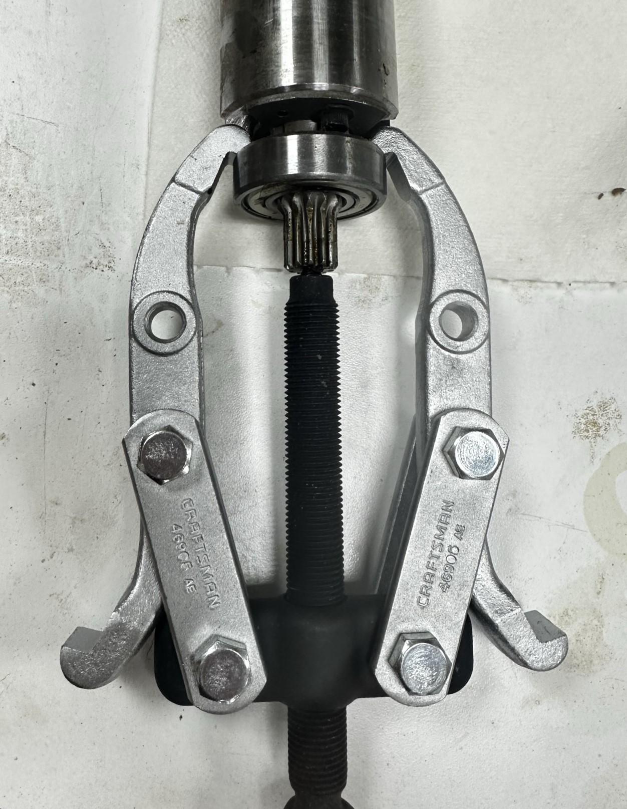
Now use the gear puller to pull the bearing off the shaft of the cutterhead:
Once the bearing is off, use a vise-grips or curved pliers to unscrew the gear from the end of the shaft (counterclockwise). Use a cloth or other padding to prevent marring of the gear, and DO NOT put the vise-grips on the teeth, only on the base of the gear, which ends at the groove indicated by the arrows in the photo:

Transfer the gear to the end of the replacement cutterhead. Assuming the new head has bearings already press-fit on, as mine did, you are ready to install the new head.
Pass the new cutterhead through the casting, leading with the worm gear end, centered in retaining cup at gearbox end, then hold it centered while pounding it home from the opposite end using a deadblow mallet, until both bearings are seated. Photo shows the geared end properly seated after driving it home with the mallet. If you back off the end-nut partway and use a rubber deadblow mallet, you probably don't need the block of wood. Note plastic wrap protecting hands from cutters.

Replace black bearing retainer on opposite end of cutterhead, using the three 4mm allen screws. Tighten these evenly and equally so that the retainer seats properly.

Remove the left-hand nut, rotate the cutterhead so that the keyway is facing up, place the key in the keyway, and slide the pulley onto the shaft and over the keyway, then replace nut and tighten. Note that if you use the new nut that came with the helical cutterhead, it may not be the same size as the original (this one was 24mm instead of the 22mm original). The photo shows the key in the keyway just prior to replacing the pulley.

Work the belt back onto the pulley, making sure it is completely on/centered, as in photo. While you're here, replace the rod that acts as the stop for the Repeat-A-Cut (yellow arrow). Note that I've repaired the broken part of the casting where the cutterhead lock attaches using super glue. So far it's holding.

Clean the outside of the gearbox if needed, then slip on over the worm gear protruding from the cutterhead shaft. You may need to rotate the cutterhead slightly for the gears to mesh. Then reattach the gearbox to the casting with the four allen screws. The photo shows the correct orientation of the gearbox prior to reattachment.

Replace the chain and cog assemblies in the order you removed them, first the left (vertical) side then the oblique set. Because the three shafts that these go on are keyed, you may need to rotate one of the sprockets to get both oriented properly to fit on the two shafts simultaneously. Both need to be pushed on at the same time as there is little slack.
The first photo shows the first chain/cogs replaced, the second photo shows both replaced. Use the spring retainer pliers to replace the three spring retainer clips.


Now turn the planer right side up. Replace the plastic grease drip catcher tray (there is a proper orientation that should be fairly obvious). Now it's time to lower the carriage back onto the four guide posts.
Before doing so, inspect the tops of the four upper guides. If you've cleared the shafts, the little support blocks that fit in the sides of the upper frame may have fallen inside or otherwise dislodged from normal position (you can inspect the lower frame to see what proper orientation looks like). See arrow in photo below. If so, I recommend removing them before lowering the carriage, as they will probably jam.

Using the deadblow mallet with or without the wood block, carefully and gently tap down on each of the four cylindrical parts of the frame that the support rods go through. The idea is to keep the frame level as it reengages the support rods, to avoid jamming or breaking the casting. Once it is engaged and level, the weight of the assembly should cause it to drop until it reaches the elevating screws.
Now replace each of the four support blocks, if they have been removed. By tugging at the black plate locking plates, there should be just enough slack to slip the guide blocks in. See photo, but note that in photo the carriage has not been lowered as far as recommended.

Temporarily reattach the height adjustment wheel, re-engage the elevating screws, and lower the carriage about 2/3.
If the carriage lock lever has disengaged from the lock mechanism, re-engage it now, making sure that it is locking in the full right position and unlocked in the full left position. If not, pull the gearing apart, move the lever one way or the other, and re-engage. Once correctly set, position the lever top center and replace the side panel.

Replace the Repeat-A-Cut door panel (you could delay doing so until after everything is up and running again, if you plan on recalibrating the Repeat-A-Cut mechanism), reattach the triangular carriage locking knob with its 4mm allen screw, and reattach the adjusting wheel with its 4mm allen screw.
Replace the bolt and washer on the top of the left hand elevating screw:

Set the left side panel in place, reattaching the rubber hand guard if this fell out during removal:

Place the four 5mm allen screws in the two side panels, then work the metal top back into position between the two side panels (may need to pull and push a bit to get it all fitting correctly). Then tighten down the screws to the guide shafts with the 5mm allen key.


If you've removed the thickness indicator, reattach now.
Check to see if there are any screws or parts you've forgotten to replace!
Plug it in and turn it on. It should be considerably quieter than the stock head. And plane figured wood like butter, with little or no tearout.
Note that you may need to recalibrate the thickness indicator and the Adjust-A-Cut stop rod with the new cutterhead. Parallelism should not have been impacted, but test a piece of wood fed into the left vs right sides of the planer with a calipers to double-check.
Congratulations on upgrading your planer!
P.S. While there were several moments of high anxiety where I thought I'd never get the planer back together intact, and it took half a day for me through trial and error, including a trip to the store for a 22mm socket, the upgrade seems to really make a difference in the quality of finish, totally worth the cost and trouble in my opinion.
These directions were really top notch, great explanations & photographs, many thanks Dan! I just completed installing the Byrd/Shelix on my TP13002, here are a few observations:
ReplyDelete1) The nut on the Byrd that secures the pulley to the cutterhead assembly is right-handed, I've reached out to Byrd to understand why the change. That said, in my case I could not use the old nut and I needed a 24mm socket.
2) I had a hard time getting the bearing retainer seated, so I ended up uninstalling the cutter head, installing the bearing retainer on the bench then sliding the assembly back in. Once I had the bearing on the worm gear side partially seated l loosely installed the bearing retainer screws to guide it into place.
3) When you're ready to put the carriage back in place and engaged with the height adjustment screws, don't forget to lower the in-feed & out-feed tables.
Again, excellent instructions, I could no have done it without them!
Thanks, Steve. That's exactly why I edited and published my personal notes on the install - so that someone else would be able to have detailed instructions and not be intimidated. Regarding your observation #3: yes of course, but thanks for making it clear.
Delete